- 8051 Program Counter
- Program For Digital Clock Using 8051 Instruction
- Assembly Code For Digital Clock Using 8051
- 8051 Instruction Set Pdf
- Program For Digital Clock Using 8051 Programming
- Program For Digital Clock Using 8051 Microcontroller
You might be seeing a wall clock running with a 1.5V battery or a digital watch running with lithium or silver oxide. But, an interesting thing is, if you want to tick a clock in real time applications, the only solution is to use RTC (Real Time Clock) to get Date and Time.
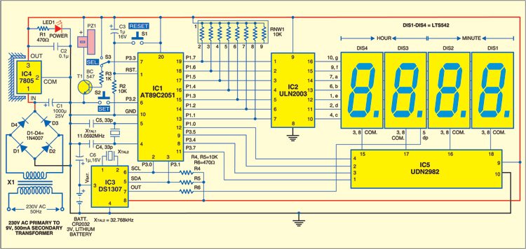
Find the Schematic, Working, Circuit Diagram, PCB Layout and code for the Digital clock using 8051 microcontroller Project. Digital Clock Circuit using 8051 and DS12C887: In this work, a real-time clock is implemented to display the time in 24 hours mode using 8051 microcontroller and RTC chip. This type of circuit is useful for displaying time and date in homes, railways, bus stands, cars, etc.
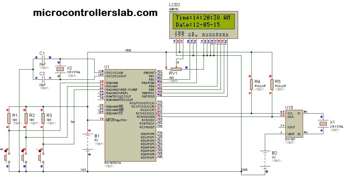
In the previous tutorial, I have explained how to use RTC DS3231 with microcontroller and display date and time on LCD.
Digital Clock in Assembly Code for a 8051 microcontroller using EdSim51 simulator. In this project, you are required to design a Digital Clock. You may use three neighbor memory addresses (RAM) to show the digital clock; for example, you may use RAM addresses 30H, 31H, and 32H respectively to show seconds, minutes, and hours (refer to Figure1). A pre-scaler scales the clock pulses from the master clock that are sent into the timer. In the case of the 8051 microcontrollers, the master clock frequency is divided by 12 and then fed into the timer. This helps to increase the accuracy of time kept but decreases the range at the same time.
In this article, I will show how to display date and time on PC using 8051 serial communication.
RTC Schematic of DS3231
RTC code for DS3231
This embedded C program evaluates the working of DS3231 RTC with 8051 Microcontroller and displays time and date on PC.
8051 Program Counter
The below code snippet shows the macros used for RTC registers. The addresses correspond to the slave address of DS3231, second, minute, hour, second, date, month, and year, hour format.
The below code shows the macros used for i2c communication with 8051.
The below code explains the serial communication with 8051 and RTC.
The header file has been created for accessing the global variables.
The delay function has been used to set some lag for sending byte by byte to PC.

Proteus Simulation
Conclusion
I hope you understand how to use Real Time Clock (RTC) to display the date and time on the serial terminal.
Program For Digital Clock Using 8051 Instruction

There are multiple ways to monitor the data. It might be an LCD, PC or a serial debugger.
This DS3231 RTC code is tested on 8051 microcontroller. The date and time will be shown on the serial terminal at 9600 baud rate. The software can be putty, real term, dock light, and hyper terminal, etc.
In this simple tutorial, we will interface the 7 segment display with 8051 microcontrollers. we will program using Assembly language or Machine language which is very essential and the mother of all recent programming languages such as C or Embedded C.
About 7 segment Display: A seven-segment is one of the most basic displays that we can display number from 0 to 9( In Binary) or 0-F (in Hexadecimal). The seven-segment display pins (a,b,c,d,e,f,g) in addition to the decimal point of both a common anode and common cathode displays are connect to port pins of LPC1768 via current limiting resistors (220 Omega).
Working principles: The Working principle of this project is very easy. The Counter will count Numbers from 0 to 9 and Loop it again and again. As the name suggests 7 segment displays with 8051 MCU, The code is written in Assembly language.

We have done some other useful tutorials using 7 segment displays such as counter from 0000 to 999 and also Full Digital clock.
Pins Configuration
Seven segments LED is a device having seven light-emitting diodes with either anode terminals (common anode or cathode) terminals. So, they form the shape of number 8.
To use this seven-segment display, once should know the pin configurations very well. As you came to know that, the display has got 9 pins in total,(Ag+DP+Common pins) but essentially, incase of Common Cathode, the display has 2 GNDs that are internally connected, so, the Sum is 9+1 = 10 pins.
Assembly Code For Digital Clock Using 8051
A 7-Segment display has 7-segments/pins named as a, b, c, b, e, f, g to form the shape of “8” and another pin called ‘h’ for a decimal point along with two extra pins for GND when it comes to Common Cathode.
Common Cathode: All the positive terminals (Anodes) of all the 8 LEDs are connected together, named as COM Cathode. So, the negative terminals are left alone with a-g
Common Anode: All the negative terminals (Cathodes) of all the 8 LEDs are connected together, named as COM A. Then, all the positive terminals are left alone with a-g so as to connect to the port.
8051 Instruction Set Pdf
Components Required
- AT89C51 Microcontroller
- 7 segment display
- Crystal oscillator
- 22pf Capacitor
- Power Source 5v-9v
Circuit Diagram
Project Code
Program For Digital Clock Using 8051 Programming
You should save the code as .asm since it’s written in Assembly language.
Project Simulation
Program For Digital Clock Using 8051 Microcontroller
That is the end of our simple tutorial. Hope you liked it, don’t forget to subscribe my channel at